Polygon Crest is a fre and open-source program. Therefore, you can use it for free of charge. However, I appreciate if you donate some money for supporting the development. For making donation, please send some money via PayPal using the following button.
I will use the donated money for upgrading my developing environment, buying books for learning new programming techniques, maintaining and adding contents in YSFLIGHT.COM. Thank you for your support!
Let's say you are making a fuselage of an airplane. You may want to first make bunch of contours based on technical drawings and then connect them with polygons. Well, making contours need a different training, so in here let's use a set of contours that I have already made for you. This example will show you how you can connect them.
This example uses the following sample file. Please download by clicking the link and save it to an appropriate folder where you store your data files.
Sample File: C172R_fuselage_contour.srf (Contour lines of Cessna 172R fuselage.)
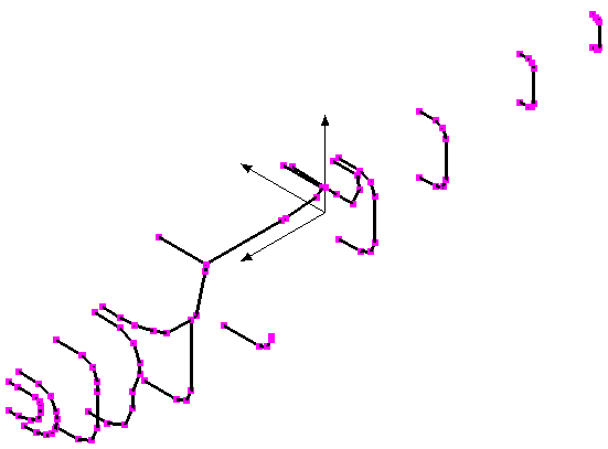
Then, select [File]->[Open], and select the file you've just downloaded. You will see the screen like the following screenshot.

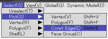
When you are able to successfully open the sample file, select [Select]->[Pick]->[Const Edges]. Actually you will need to select const edges many times while you are editing the model, you can also press Shift+E instead of selecting the menu item.
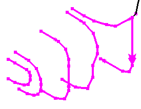
Then, select five const edges (contours) from the forward to aft. You may want to move/rotate/zoom your view point so that you can see the nose section well. Please read this for viewing control.
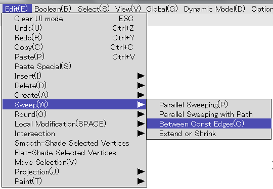
Then, select [Edit]->[Sweep]->[Between Const Edges].
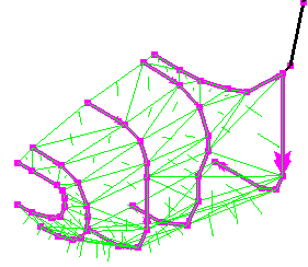
Make sure the normal vectors (green lines) are pointing outward, and then click on the [Sweep] button.
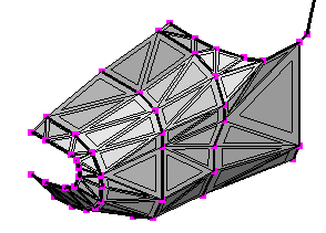
You can make the polygons for the tail section similarly. Select [Select]->[Pick]->[Const Edges] or press Shift+E key. Then select four aft-most const edges. The order matters. Make sure you pick forward-most const edge first, and then to the aft.
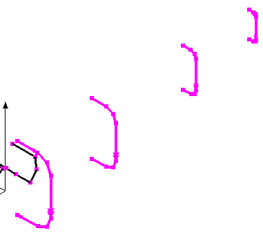
Then select [Edit]->[Sweep]->[Between Const Edges], and make sure the normal vectors are pointing outward, and then click on the [Sweep] button.
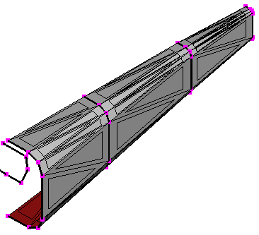
Side of the middle section of the fuselage comes a door and windows, and the top of the fuselage will be covered by the wing in Cessna 172. You need to use a different method to patch those parts. But, you can use the same technique for the nose and tail sections to make the mid-bottom part of the fuselage. But, to do so, you first need to split two const edges.
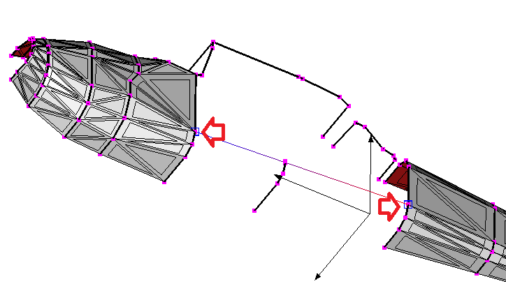
Use viewing control so that you can see the bottom (belly) of the airplane. And select [Select]->[Pick]->[Vertices], or you can press Shift+V as shortcut. Then, click on the vertices pointed by red arrows in the following screenshot. You don't have to click if it is too small. You can left-drag to specify a rectangular region, and all vertices inside the rectangle will be added to the selection.
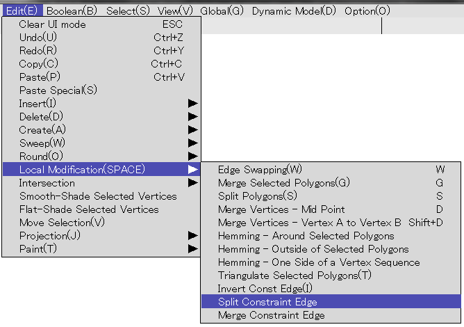
Then click on [Edit]->[Local Modifications]->[Split Const Edges]. This will split two const edges at the selected vertices.
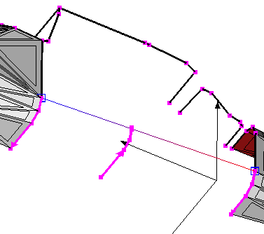
Then select [Select]->[Pick]->[Const Edges] or press Shift+E, and click on the three const edges highlighted below.
Select [Edit]->[Sweep]->[Between Const Edges]. Make sure the normal vectors are pointing outward, and then click on the [Sweep] button.
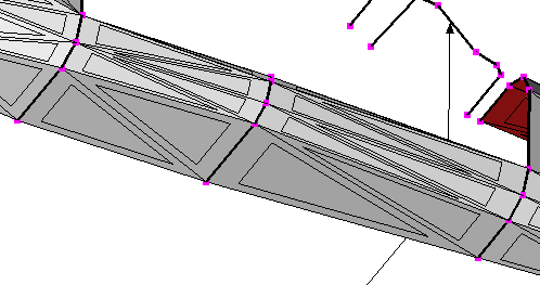
The rest of polygons of the fuselage need to be created by different methods. Which will be explained in other tutorials.
