Polygon Crest is a fre and open-source program. Therefore, you can use it for free of charge. However, I appreciate if you donate some money for supporting the development. For making donation, please send some money via PayPal using the following button.
I will use the donated money for upgrading my developing environment, buying books for learning new programming techniques, maintaining and adding contents in YSFLIGHT.COM. Thank you for your support!
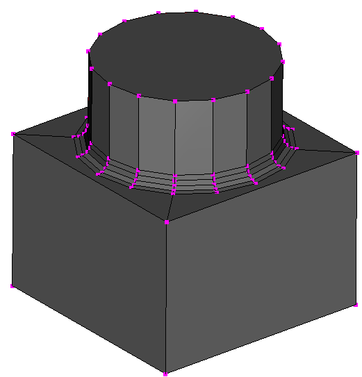
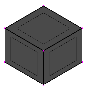
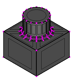
This example explains the steps to create a solid shape shown below. There are four big steps (1) creating a rectangular solid, (2) creating a cylindrical shape, (3) making a union of the rectangular solid and cylindrical shape, and (4) round the corner between the rectangular solid and the cylindrical shape.

A C-language programming starts with "Hello World!". A 3D modeling starts with creating a rectangular solid. I think it's a very easy and good first step.
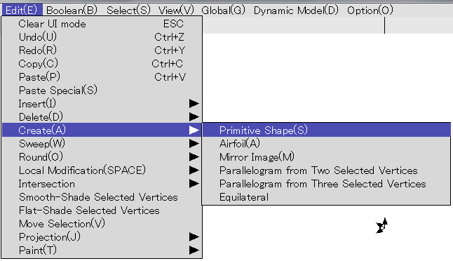
Select [Edit]->[Create]->[Primitive Shape]
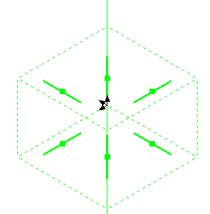
You can specify a rectangular solid. Left-click on the line on top, and drag it down a little bit.
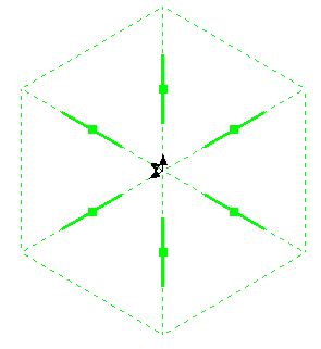 =>
=>
Press SPACE key to generate a rectangular solid. Easy enough?
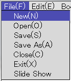
Next step is creating a cylindrical shape. We want to take a union with the rectangular solid created in the first step. For that purpose, it needs to be created as a separate model. Select [File]->[New] to create a new model.
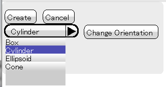
Then select [Edit]->[Create]->[Primitive Shape], just like you did in the first step, and select [Cylinder] in the primitive-shape dialog.
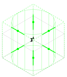
Then click on [Change Orientation] button until the cylinder becomes vertical. (I am assuming you haven't changed the viewing orientation.)
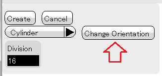
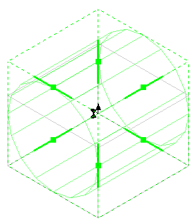 =>
=>
You are almost ready to create a cylindrical shape, but we want to make it smaller diameter so that there is a room for rounding. Click on [Center] and [Size] buttons on the rectangular-solid region dialog. And then type in 0 1 0 as center, and 6 10 6 as size. (Make sure you click on [Center] and [Size] buttons before typing in the number. Otherwise, the numbers you type in will have a different meaning. If you did so, click on [Center] and [Size] buttons again, and then type in the numbers.)

Click on [Set] button. Cylindrical shape on the window will be drawn thinner.
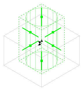
Press SPACE key to create a cylinder.
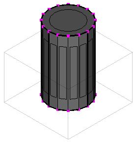
Now you have two separate models, a rectangular solid and a cylindrical shape. Let's unite them. This operation is called a Boolean operation. There are many different types of boolean operations. In this example, we use an operation called union.
Select [Boolean]->[Union].
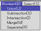
Then click on one of the edges of the rectangular solid and wait. (Well, I should make it sub-thread so that you can still have control, but I haven't done so yet. So, you need to wait.)
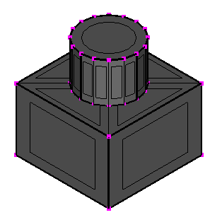
In this example, the operation should succeed. However, when you are using a boolean operation on your own models, make sure the models are closed solids. Boolean operations in this program assumes that the models are closed solid with no self intersections. For example, if you create a rectangular solid, and delete one of the faces, the model is no longer closed. If you feed an open model to a boolean operation, the operation may fail. I hope I made the program safe enough so that it doesn't crash so often, but it may crash if the model is too broken (to be a solid).
Let's round off the corner between the cylinder and the rectangular solid. This program has an "incorrect" rounding function. Why incorrect? I implemented a very simple way of rounding calculation. It is simple and somewhat rounds the corners, but not correct.
In fact, I've been working on finite-element meshing research, and rounded corners (fillets) are arch enemy of mesh generators. I don't like fillets. I had been battling the fillets from day one of my meshing research career. One day I dominate the galaxy and ban all fillets together. Nonetheless, until I dominate the galaxy, I need rounded models to study a new and better methods for dealing with this kind of round corners. So, I added this feature.
You probably notice that the boundary between the cylinder and the rectangular solid is drawn with a thick line. It is called a constraint edge, or const edge. You can use const edges for many purposes in this program such as specifying contours, extrusion path, etc. In this example, you can use it for specifying where to round.
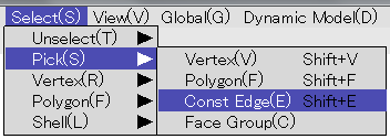
First select the const edge between the cylinder and the rectangular solid. Select [Select]->[Pick]->[Const Edges]. By the way, you will use this function many times when you create a more complex model. You can press Shift+E to select a const edge by picking, and press T key to unselect all.
Then click on the const edge between the cylinder and the rectangular solid.
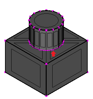
Then select [Edit]->[Round]->[Along Selected Vertex Sequence or Const Edge].
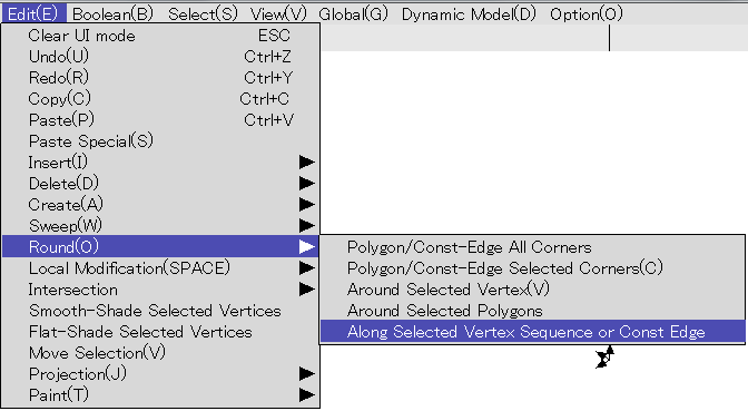
Click on [OK] on the rounding dialog.

Done!
You can save the model by [File]->[Save] or [Save As].