|
Disclaimer: I will not be responsible for any damages caused by the information in here. If you cannot agree with it, please leave and do not use the programs and schematics available from this page. Sending a wrong infra-red signal may cause unexpected behavior of the devices. ESPECIALLY, DO NOT USE THIS TRANSMITTER FOR THE DEVICES THAT EMITS HEAT!
Here you can download schematic, Arduino source, and control program for capturing and playing back infra-red remote signal. I first started this project to capture infra-red signal emitted from a keyboard for a Fujitsu-built retro PC called FM77AV (1985).
With help from many people I already had succeeded in sending keyboard signals to my FM77AV. However, I was not certain if the signal I was generating was same as the signal emitted by the original keyboard. Anyway, I wanted to leave the information as a historic technical information.
Then I learned that infra-red signal is not simply 100us on, 100us of, kind of plain pulses. It is modulated in 38KHz PWM, for example, if I need to make 100us HIGH signal, I need to send four pulses of 13us ON/13us OFF.
First I tried to capture the signals using a product called IRToy. But, it was not fast enough to capture 100us signals from my FM77AV keyboard. Then I picked a random Infra-red LED and photo-diode pairs from Amazon, and tried to make a capture circuit, which was too slow again. As my final attempt, I picked an infra-red photo-diode that is said to be "fast". Then finally I was able to capture PWM pulses. By the way, as always I got enormous help from Mr. Apollo while building the receiver.
You need one Arduino for receiver, for another for transmitter. Transmission can be done with Arduino UNO, but recording needs a larger buffer to store pulse widths, and Arduino Mega is recommended. The source code is good for both Arduino UNO and Mega, but if you use Arduino UNO, you may not be able to capture entire signal. Or, if you are not interested in seeing PWM pulses, you can keep your IR remote very close to the photo diode, like 1mm, and capture the pulse. Then the emission is so strong that individual PWM pulses will be merged together. This way Arduino UNO may be able to capture TV, AC, and other remotes.
You will need a control program that runs on Windows to use the transmitter and receiver. You can download from the following link:
[Infra-Red Transmitter Command]
[Source in GitHub (public/src/ir_transceiver)]
When you try to execute the programs above, you may see a warning message that says the program was not signed. Please click on the "Run Anyway" if you trust me. Or, if you build from the source, you won't get the message. Now, the freedom of programming is at risk. Big companies, Apple, Google, Microsoft, etc., has done a lot of fantastic jobs and contributed to the advance of the computer technologies. There is no doubt about that. However, not everything they did was right. Some people apparently want to dominate and control the programmers. Those people are trying to take away the right to publish programs from individual programmers. To prevent Windows from showing "unsigned program" warning, I used to be able to buy a code-signing certificate by paying outrageous price every year. Now, even if I am willing to pay outrageous price, certificate authorities no longer sell a certificate to individual programmers. It is very important to make clear who wrote the program. It is a very good way of increasing security. It is not a problem is someone does a business for managing those code-signing certificate. HOWEVER, it is VERY WRONG that a private company can arbitrarily decide who can have code-signing certificate. I know it is a losing battle. Very few people listens to those who demand freedom of programming. But, it is wrong. Everyone should have right to freely publish a program. Nothing might change. But, I don't die without resisting.
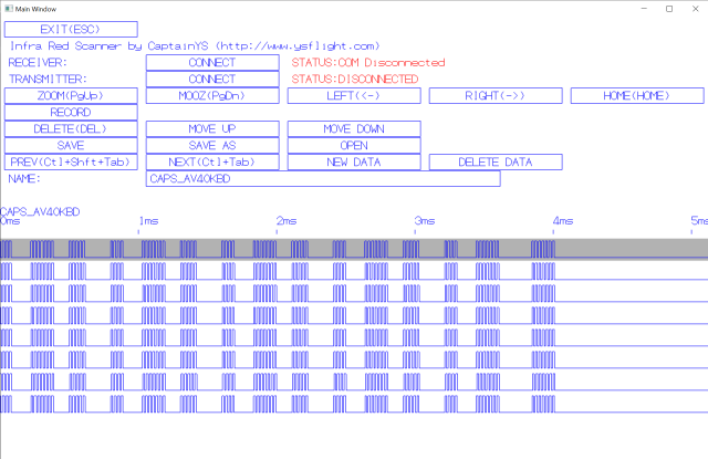
With the transceiver GUI, you can record and playback infrared signals. If you start from the command line, you can specify the file name of the recorded infra-red signal (just in a plain text format), specify receiver COM port by -recv (com-port number), or specify transmitter COM port by -trans (com-port number). You can just specify the port number. Not like "COM1". If the receiver Arduino is connected to COM1, just say -recv 1. I am trying to expand it for Linux and macOS. In that case, you would specify the path to the COM port.
If you start without command line, first you connect to the receiver by clicking "CONNECT" button next to the "RECEIVER:" then specify the port. You can check which port your Arduino is connected by opening Device Manager. Just type in the number. No need to type "COM".
In this program you can record multiple buttons in one file, and one button can store multiple samples. There is no limitation in how many samples you can store per button (until you fill up the computer memory), but the program shows only as much as it fits in the Window. Actually you only need one good sample. The rest are just for verification. Actually it was interesting to see that my ViewSonic TV remote button was sending two different (alternating) signals for every button press, but even in that case you need only one. To delete unnecessary samples, select a sample by up and down arrow, and press "Delete" key or "DELETE" button.
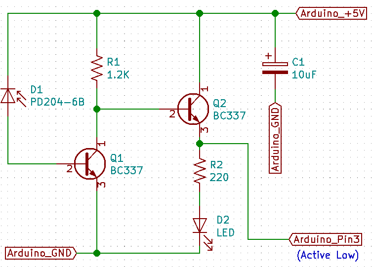
To sample an IR button signal, click on "RECORD" button and turn it on. Then, keep your infrared remote like one to two inches away from the infrared photo diode (PD204-6B), and aim straight into the photo diode, and press the button on your remote. If you hold the button too long, you may end up recording multiple samples, but no harm. Probably the second signal may be sent while the receiver is sending the data to the PC, in which case you will see partial signal, but as long as your first sample is good, you are good. To capture the behavior of PWM, the resistor for the photo diode is chose for low sensitivity. If you push the button more than two inches away, you probably won't see a signal.
Maybe it's a good idea to record same button multiple times and compare the wave pattern.
For each button, click on the text box next to "NAME:" to specify the name of the button. As you can see, I made it with a very cheap GUI. You can only enter alphabets and numbers.
To start recording the next button, click on "NEW DATA" and do the same thing for the next button.
I tried to be careful so that the program does not crash (I am teaching programming, I should be able to.) But, no human is perfect. I might have missed something. So, I recommend to save your data frequently by pressing "SAVE" button.
To flip through the recorded data, press Ctrl+Tab or Ctrl+Shift+Tab, or click on "NEXT" and "PREV".
To transmit what you recorded, first connect your transmitter by clicking on "CONNECT" button next to "TRANSMITTER:" Then enter the port number. When the transmitter is ready, you will see "TRANSMIT" button. When you click it, the first sample of the current data is transmitted from the Arduino transmitter.
Once you recorded your remote, you can transmit a button signal from the command. For example, you can type in the command prompt as:
.\irsend datafile.txt port_name "button_name1" "button_name2" "button_name3" -wait 500
datafile.txt is your sample data, port_name should be the port number. "button_name1" to "button_name3" are the button names you specified while you were recording, -wait 500 means keep 500 milliseconds interval between buttons.
Receiver Schematic

Receiver + Arduino Photo
Arduino Source for Receiver
/*

Redistribution and use in source and binary forms, with or without modification,
are permitted provided that the following conditions are met:

1. Redistributions of source code must retain the above copyright notice,
   this list of conditions and the following disclaimer.

2. Redistributions in binary form must reproduce the above copyright notice,
   this list of conditions and the following disclaimer in the documentation
   and/or other materials provided with the distribution.

THIS SOFTWARE IS PROVIDED BY THE COPYRIGHT HOLDERS AND CONTRIBUTORS "AS IS"
AND ANY EXPRESS OR IMPLIED WARRANTIES, INCLUDING, BUT NOT LIMITED TO,
THE IMPLIED WARRANTIES OF MERCHANTABILITY AND FITNESS FOR A PARTICULAR
PURPOSE ARE DISCLAIMED. IN NO EVENT SHALL THE COPYRIGHT HOLDER OR CONTRIBUTORS
BE LIABLE FOR ANY DIRECT, INDIRECT, INCIDENTAL, SPECIAL, EXEMPLARY, OR
CONSEQUENTIAL DAMAGES (INCLUDING, BUT NOT LIMITED TO, PROCUREMENT OF SUBSTITUTE
GOODS OR SERVICES; LOSS OF USE, DATA, OR PROFITS; OR BUSINESS INTERRUPTION)
HOWEVER CAUSED AND ON ANY THEORY OF LIABILITY, WHETHER IN CONTRACT, STRICT
LIABILITY, OR TORT (INCLUDING NEGLIGENCE OR OTHERWISE) ARISING IN ANY WAY OUT
OF THE USE OF THIS SOFTWARE, EVEN IF ADVISED OF THE POSSIBILITY OF SUCH DAMAGE.
 */

enum
{
  STATE_STANDBY,
  STATE_READY_TX,
};


// Timer 1 is used for recording pulse timings.
// Don't care about overflow.  Just record 16-bit values.
// Later overflow will be taken into account.

// Timer 2 is used for detecting long IR off.
// Using 1024x scaling and if it goes up to 255, it is taken as IR signal is done.


#if defined(__AVR_ATmega2560__)    // Arduino Mega 2560
  #define PULSE_BUF_LEN 3072

  #define Pin3State (PINE&_BV(5))

  #define SetPin0High  PORTE|=_BV(0);
  #define SetPin0Low   PORTE&=~_BV(0);
  #define SetPin1High  PORTE|=_BV(1);
  #define SetPin1Low   PORTE&=~_BV(1);
  #define SetPin2High  PORTE|=_BV(4);
  #define SetPin2Low   PORTE&=~_BV4();
  #define SetPin3High  PORTE|=_BV(5);
  #define SetPin3Low   PORTE&=~_BV(5);
  #define SetPin4High  PORTG|=_BV(5);
  #define SetPin4Low   PORTG&=~_BV(5);
  #define SetPin5High  PORTE|=_BV(3);
  #define SetPin5Low   PORTE&=~_BV(3);
  #define SetPin6High  PORTH|=_BV(3);
  #define SetPin6Low   PORTH&=~_BV(3);
  #define SetPin7High  PORTH|=_BV(4);
  #define SetPin7Low   PORTH&=~_BV(4);

  #define SetPin8High  PORTH|=_BV(5);
  #define SetPin8Low   PORTH&=~_BV(5);
  #define SetPin9High  PORTH|=_BV(6);
  #define SetPin9Low   PORTH&=~_BV(6);
  #define SetPin10High PORTB|=_BV(4);
  #define SetPin10Low  PORTB&=~_BV(4);
  #define SetPin11High PORTB|=_BV(5);
  #define SetPin11Low  PORTB&=~_BV(5);
  #define SetPin12High PORTB|=_BV(6);
  #define SetPin12Low  PORTB&=~_BV(6);
  #define SetPin13High PORTB|=_BV(7);
  #define SetPin13Low  PORTB&=~_BV(7);
#elif defined(__AVR_ATmega328P__)          // Arduino Uno (Can be Nano)
  #define PULSE_BUF_LEN 768
  #define Pin3State (PIND&_BV(3))

  #define SetPin0High  PORTD|=_BV(0);
  #define SetPin0Low   PORTD&=~_BV(0);
  #define SetPin1High  PORTD|=_BV(1);
  #define SetPin1Low   PORTD&=~_BV(1);
  #define SetPin2High  PORTD|=_BV(2);
  #define SetPin2Low   PORTD&=~_BV(2);
  #define SetPin3High  PORTD|=_BV(3);
  #define SetPin3Low   PORTD&=~_BV(3);
  #define SetPin4High  PORTD|=_BV(4);
  #define SetPin4Low   PORTD&=~_BV(4);
  #define SetPin5High  PORTD|=_BV(5);
  #define SetPin5Low   PORTD&=~_BV(5);
  #define SetPin6High  PORTD|=_BV(6);
  #define SetPin6Low   PORTD&=~_BV(6);
  #define SetPin7High  PORTD|=_BV(7);
  #define SetPin7Low   PORTD&=~_BV(7);

  #define SetPin8High  PORTB|=_BV(0);
  #define SetPin8Low   PORTB&=~_BV(0);
  #define SetPin9High  PORTB|=_BV(1);
  #define SetPin9Low   PORTB&=~_BV(1);
  #define SetPin10High PORTB|=_BV(2);
  #define SetPin10Low  PORTB&=~_BV(2);
  #define SetPin11High PORTB|=_BV(3);
  #define SetPin11Low  PORTB&=~_BV(3);
  #define SetPin12High PORTB|=_BV(4);
  #define SetPin12Low  PORTB&=~_BV(4);
  #define SetPin13High PORTB|=_BV(5);
  #define SetPin13Low  PORTB&=~_BV(5);

  #define SetPin9and10Low PORTB&=~(_BV(1)|_BV(2));

//#elif defined(__AVR_ATMega4809__)          // Arduino Nano Every
//#elif defined(__AVR_ATmega328__)           // Arduino Nano?
//#elif defined(__AVR_ATmega32U4__)          // Arduino Leonardo
//  #elif defined(__AVR_ATmega__)
//  #elif defined(__AVR_ATmega__)
//  #elif defined(__AVR_ATmega__)
#else
  #error Unable to identify Board Type
#endif


volatile int state=STATE_STANDBY;
volatile unsigned int nBufFilled=0;
volatile unsigned int pulseBuf[PULSE_BUF_LEN];


void PinChange(void)
{
  TCNT1=0;

  if(STATE_STANDBY!=state)
  {
    return;
  }

  SetPin13High;

  while(nBufFilled<PULSE_BUF_LEN)
  {
    while(0==Pin3State)
    {
    }

    pulseBuf[nBufFilled]=TCNT1;
    ++nBufFilled;

    // Infra-Red OFF (Pin3=Active Low)
    TCNT2=0;
    while(0!=Pin3State)
    {
      if(255==TCNT2)
      {
        goto END_OF_SIGNAL;
      }
    }

    pulseBuf[nBufFilled]=TCNT1;
    ++nBufFilled;
  }
END_OF_SIGNAL:

  SetPin13Low;
  state=STATE_READY_TX;
}


void ClearBuffer(void)
{
  nBufFilled=0;
  for(int i=0; i<PULSE_BUF_LEN; ++i)
  {
    pulseBuf[i]=0;
  }
}

void setup()
{
  state=STATE_STANDBY;
  ClearBuffer();


  // Reset timer 1
  TCCR1A=0;
  // TCCR1B=bit(CS10); // No Pre-Scaling
  TCCR1B=bit(CS11); // 8x Pre-Scaling
  OCR1A=0;
  OCR1B=0;
  TCNT1=0;

  TCCR2A=0;
  // TCCR2B=bit(CS20); // No Pre-Scaling
  // TCCR2B=bit(CS21); // 8x Pre-Scaling
  TCCR2B=bit(CS20)|bit(CS21)|bit(CS22); // 1024x Pre-Scaling
  OCR2A=0;
  OCR2B=0;
  TCNT2=0;


  pinMode(3,INPUT);
  pinMode(13,OUTPUT);
  attachInterrupt(digitalPinToInterrupt(3),PinChange,FALLING);

  Serial.begin(115200);
}

void loop()
{
  if(STATE_READY_TX==state)
  {
    Serial.begin(115200);
    Serial.println("Begin");
    long int total=0;
    unsigned long int prevPtr=0;
    unsigned long int basePtr=0;
    int balance=0;
    for(int i=0; i<nBufFilled; ++i)
    {
      if(0<i && pulseBuf[i]<pulseBuf[i-1])
      {
        basePtr+=0x10000;
      }
      unsigned long int curPtr=basePtr+pulseBuf[i];
      if(0!=(curPtr&1)) // 1 tick = 0.5us.  Need to make everything even, and send tick/2.
      {
        if(0<balance && prevPtr+2<curPtr)
        {
          --curPtr;
          --balance;
        }
        else
        {
          ++curPtr;
          ++balance;
        }
      }
      unsigned long int dt=curPtr-prevPtr;
      prevPtr=curPtr;

      Serial.print(dt/2);
      Serial.print(" ");

      total+=dt;
    }

    Serial.println("");
    Serial.println("End");
    Serial.print("Total=");
    Serial.print((long int)total);
    Serial.println("");
    Serial.print("nSample=");
    Serial.print(nBufFilled);
    Serial.println("");
    Serial.end();

    ClearBuffer();
    state=STATE_STANDBY;
  }

  TCCR0A=0;
  TCCR0B=0;
}
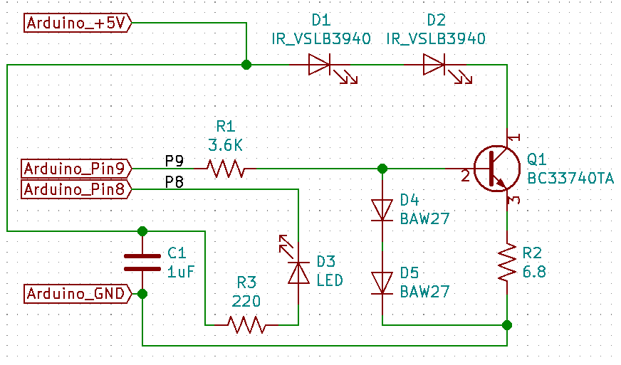
Transmitter Schematic

Transmitter + Arduino Photo
Transmitter + Arduino PCB Version
Arduino Source for Transmitter
/*
38KHz 50% duty cycle Infra-Red Signal Emitter
Copyright 2019 CaptainYS (http://www.ysflight.com)  All rights reserved.

Redistribution and use in source and binary forms, with or without modification,
are permitted provided that the following conditions are met:

1. Redistributions of source code must retain the above copyright notice,
   this list of conditions and the following disclaimer.

2. Redistributions in binary form must reproduce the above copyright notice,
   this list of conditions and the following disclaimer in the documentation
   and/or other materials provided with the distribution.

THIS SOFTWARE IS PROVIDED BY THE COPYRIGHT HOLDERS AND CONTRIBUTORS "AS IS"
AND ANY EXPRESS OR IMPLIED WARRANTIES, INCLUDING, BUT NOT LIMITED TO,
THE IMPLIED WARRANTIES OF MERCHANTABILITY AND FITNESS FOR A PARTICULAR
PURPOSE ARE DISCLAIMED. IN NO EVENT SHALL THE COPYRIGHT HOLDER OR CONTRIBUTORS
BE LIABLE FOR ANY DIRECT, INDIRECT, INCIDENTAL, SPECIAL, EXEMPLARY, OR
CONSEQUENTIAL DAMAGES (INCLUDING, BUT NOT LIMITED TO, PROCUREMENT OF SUBSTITUTE
GOODS OR SERVICES; LOSS OF USE, DATA, OR PROFITS; OR BUSINESS INTERRUPTION)
HOWEVER CAUSED AND ON ANY THEORY OF LIABILITY, WHETHER IN CONTRACT, STRICT
LIABILITY, OR TORT (INCLUDING NEGLIGENCE OR OTHERWISE) ARISING IN ANY WAY OUT
OF THE USE OF THIS SOFTWARE, EVEN IF ADVISED OF THE POSSIBILITY OF SUCH DAMAGE.
 */


#define SERIAL_BPS 115200
// Confirmed to work up to 440000bps.
// Stopped working at 460000bps.
// Not tested between 440000 and 460000bps.


#define RECVBUF_SIZE 384
int nRecvBuf=0;
unsigned char recvBuf[RECVBUF_SIZE];
unsigned int cycle[RECVBUF_SIZE/2];
bool transmitMode=false;
unsigned long lastDataReceivedTime=0;
unsigned char processingCmd=0;


unsigned char pulseWidthTable[30];
const unsigned char pulseWidthSource[3]={100,125,175};


#define CMD_RESET 0
#define CMD_IRMAN_COMPATIBLE_MODE 'R'
#define CMD_VERSION 'V'
#define CMD_SELFTEST 't'
#define CMD_SAMPLERMODE 'S'
#define CMD_ENABLE_BYTECOUNT 0x24
#define CMD_ENABLE_TRANSMISSION_NOTIFY 0x25
#define CMD_ENABLE_HANDSHAKE 0x26
#define CMD_TRANSMIT_MICROSEC 0x80
#define CMD_TRANSMIT_30BIT_100US 0x81

#define NOTIFY_READY 'C'
#define NOTIFY_FAIL 'F'

// 50% duty cycle: On and off within 1/38000 sec.  Must togle every 1/76000 sec.
#define TIMER_THRESHOLD_38K_WITH_1xPRESCALE ((F_CPU/38000)/2)
// Experiment with FM77AV40 IR LED receiver:  19000Hz No response 34000-36000 drops key.  38000 perfect.  40000 drops keys.

#define PWM_TIMER_THRESHOLD TIMER_THRESHOLD_38K_WITH_1xPRESCALE

// Succeeded Xfinity remote

#define PIN_OC1A 9
#define PIN_OC1B 10
#define PIN_OC2A 11
#define PIN_OC2B 3

#define PIN_POWER 13
#define PIN_STATUS 8

// PIN9=PB1 (PortB bit 1)
#define SetPin9High  PORTB|=_BV(1);
#define SetPin9Low   PORTB&=~_BV(1);
// PIN10=PB2 (PortB bit 2)
#define SetPin10High PORTB|=_BV(2);
#define SetPin10Low  PORTB&=~_BV(2);
// PIN11=PB3 (PortB bit 3)
#define SetPin11High PORTB|=_BV(3);
#define SetPin11Low  PORTB&=~_BV(3);
// PIN3=PD3 (PortD bit 3)
#define SetPin3High  PORTD|=_BV(3);
#define SetPin3Low   PORTD&=~_BV(3);

// PIN13=PB5 PortB bit 5
#define SetPin13High PORTB|=_BV(5);
#define SetPin13Low PORTB&=~_BV(5);
// PIN8=PB0 Port B bit 0
#define SetPin8High PORTB|=_BV(0);
#define SetPin8Low PORTB&=~_BV(0);

#define SetPin9and10Low PORTB&=~(_BV(1)|_BV(2));


#define SET_CTC_MODE {TCCR1B=bit(CS10)|bit(WGM12);}
// TCCR1B  WGM10=0,WGM11=0,WGM12=1 means CTC mode
//         CS10=1,CS11=0,CS12=0 means 1x pre-scale (no scaling).
//         CS10=0,CS11=0,CS12=0 means timer stop.

#define SET_OC1A_OC1B_TOGGLE {TCCR1A=bit(COM1A0)|bit(COM1B0);}
// ATmega 328 datasheet pp.134
// TCCR1A  COM1A0=1, COM1B0=1 means toggle OC1A and OC1B on compare match

#define SET_OC1A_OC1B_LOW {TCCR1A=(bit(COM1A1)|bit(COM1B1));TCCR1C=(bit(FOC1A)|bit(FOC1B));TCCR1C=0;}
// TCCR1A=(bit(COM1A1)|bit(COM1B1));  // Clear OC1A low on compare match
// TCCR1C=(bit(FOC1A)|bit(FOC1B));    // Force match
// TCCR1C=0;                          // Do I need to clear?


// Failed Attmept:
// For each HIGH pulse, force OC1A to be HIGH, and then start timer.  This approach didn't work.
// Probable reason is that it makes the first duty cycle slightly shorter.
// This method FM77AV40 misses one in every 80 to 100 key strokes.


void setup() {
  for(int i=0; i<30; ++i)
  {
    pulseWidthTable[i]=pulseWidthSource[i%3];
  }

  Serial.begin(SERIAL_BPS);

  pinMode(PIN_POWER,OUTPUT);
  pinMode(PIN_STATUS,OUTPUT);

  pinMode(PIN_OC1A,OUTPUT);
  pinMode(PIN_OC1B,OUTPUT);
  pinMode(PIN_OC2A,OUTPUT);
  pinMode(PIN_OC2B,OUTPUT);

  // Reset timers 1 and 2
  TCCR1A=0;
  TCCR1B=0;
  TCCR2A=0;
  TCCR2B=0;
  TCNT1=0;
  TCNT2=0;

  // Timer 1 (8-bit) for 38K PWM IR LED output
  // ATmega 328 datasheet pp.134
  OCR1A=PWM_TIMER_THRESHOLD;
  OCR1B=0;

  SET_OC1A_OC1B_LOW;

  // Timer 2 for measuring 1us tick.
  TCCR2A=0;
  TCCR2B=bit(CS21);
  // CS20=0,CS21=1,CS22=0 means 8x pre-scaling.  0.5us per tick.  ATmega328 datasheet pp.162
  OCR2A=0;
  OCR2B=0;

  SetPin13Low;
  SetPin8Low;
  SetPin9and10Low;
}

void SendCycleHWPWM(unsigned int cycle[])
{
  noInterrupts();

  TCNT1=0;
  SET_CTC_MODE;
  SET_OC1A_OC1B_LOW;
  // Now pins 9 and 10 are under control of Timer 1, OC1A, OC1B both low.
  // Pin9=OC1A
  // Pin10=OC1B

  for(int i=0; cycle[i]!=0xffff; i+=2)
  {
    TCNT2=0;

    TCNT1=PWM_TIMER_THRESHOLD-8;
    // Timer 1 pre-scalar is 1x.
    // Need to start toggling within 8 cycles.  0.5us error.
    SET_OC1A_OC1B_TOGGLE;

    auto w=cycle[i]<<1;
    while(TCNT2<w)
    {
      if(240<=TCNT2)
      {
        TCNT2=0;
        w-=240;
      }
    }

    TCNT2=0;
    SET_OC1A_OC1B_LOW;
    w=cycle[i+1]<<1;
    while(TCNT2<w)
    {
      if(240<=TCNT2)
      {
        TCNT2=0;
        w-=240;
      }
    }
  }

  SET_OC1A_OC1B_LOW;
  SetPin9and10Low;

  interrupts();
}

void MakeCycle(unsigned int cycle[],int nSample,unsigned char sample[])
{
  unsigned char k=0;
  switch(processingCmd)
  {
  case CMD_TRANSMIT_MICROSEC:
    {
      for(int i=0; i+1<nSample && (sample[i]!=0xff || sample[i+1]!=0xff); i+=2)
      {
        cycle[k]=(sample[i]<<8);
        cycle[k]+=sample[i+1];
        ++k;
      }
    }
    break;
  case CMD_TRANSMIT_30BIT_100US:
    {
      unsigned char samplePtr=0,sampleBit=1;
      cycle[k]=0;
      for(unsigned char i=0; i<30; ++i)
      {
        bool currentBit=((~k)&1);
        bool nextBit=(sample[samplePtr]&sampleBit);
        if(currentBit!=nextBit)
        {
          ++k;
          cycle[k]=0;
        }
        cycle[k]+=pulseWidthTable[i];

        if(128==sampleBit)
        {
          ++samplePtr;
          sampleBit=1;
        }
        else
        {
          sampleBit<<=1;
        }
      }
      ++k;
    }
    break;
  }
  cycle[k]=0;
  k+=(k&1); // Force it to be even.
  cycle[k  ]=0xffff;
  cycle[k+1]=0xffff;
}

void Transmit()
{
  SetPin8High;
  MakeCycle(cycle,nRecvBuf,recvBuf);
  SendCycleHWPWM(cycle);

  while(0==Serial.availableForWrite());
  Serial.write(NOTIFY_READY);

  transmitMode=false;

  SetPin8Low;
}

void loop() {
  bool received=false;
  while(0<Serial.available())
  {
    auto recvByte=Serial.read();
    if(true!=transmitMode)
    {
      processingCmd=recvByte;
      if(CMD_TRANSMIT_MICROSEC==recvByte ||
         CMD_TRANSMIT_30BIT_100US==recvByte)
      {
        transmitMode=true;
        nRecvBuf=0;
      }
      else if(CMD_IRMAN_COMPATIBLE_MODE==recvByte)
      {
        Serial.println("OK");
      }
      else if(CMD_VERSION==recvByte)
      {
        Serial.println("A277");
      }
      else if(CMD_SAMPLERMODE==recvByte)
      {
        Serial.println("S77");
      }
    }
    else
    {
      recvBuf[nRecvBuf++]=recvByte;
      if(CMD_TRANSMIT_30BIT_100US==processingCmd && 4<=nRecvBuf)
      {
        Transmit();
      }
      else if(RECVBUF_SIZE<=nRecvBuf)
      {
        Transmit();
      }
      else if(2<=nRecvBuf && 0xff==recvBuf[nRecvBuf-1] && 0xff==recvBuf[nRecvBuf-2])
      {
        Transmit();
      }
    }
    received=true;
  }

  unsigned long t=millis();
  if(true==received)
  {
    lastDataReceivedTime=t;
  }
  else
  {
    // Second mode of failure.
    // In transmit mode, the FIFO buffer is overwhelmed and starts losing bytes.
    // The terminator 0xffff won't be caught, however, 0x03 included in the
    // pulse-width data put it into the transmitMode again, and never recover.
    // To get out of this mode, the user needs to release the key for 100ms.
    // If no byte is received for 100ms, the program goes back to command mode.
    if(true==transmitMode)
    {
      if(t<lastDataReceivedTime ||   // Timer overflow
         100<t-lastDataReceivedTime) // 100ms no transmittion from host
      {
        transmitMode=false;
        Serial.write(NOTIFY_FAIL);
        Serial.write(NOTIFY_READY);
      }
    }
  }
}
| Comments are welcome.
Send E-Mail to:
|