|
[FM-7/77 RS232C Card (KiCad format)]
Updated 2022/04/16 The new design allows to select COM0 or COM1 by jumper pins. If configured as COM1, it can be used in AV40 and newer models.
I don't know how many of you are interested in classic Japanese computers. But, if you do, you may know about FM-7. FM-7 is often on sale on Yahoo auction. It is relatively easy to get a working unit from Yahoo auction via buyee.jp.
To set it up, you need to jump through several hoops. Hooking up to a monitor. Finding a keyboard if your unit didn't come with a keyboard. One of those hoops is how to transfer data to/from a Windows or Mac computer.
If you own a FM77AV40 or newer, you then can write an easy F-BASIC program to transfer program/data from a PC via serial connection. By the way, 25-pin serial port of FM77AV40 is OFF when it starts. You may type:
POKE &HFD0C,5
POKE &HFD0B,16
EXEC -512
from the F-BASIC console and wait for 30 seconds or so. The system restarts and you can use serial port from F-BASIC.
If you have an older model, a 25-pin serial port does not exist. You may fabricate an audio-cassette interface cable to feed data through the audio-cassette interface. You can use my Disk2Tape utility to convert a D77-format disk image to a series of .WAV files, and then burn a floppy disk using FM77 series computer. However, you need to own a PC with a sound unit that can raise the volume loud enough so that FM-7/77 can listen. My 2008 MacBook Pro succeeded. Dell XPS desktop also succeeded. My ThinkPad X230T and X250 failed. New Dell desktop also failed.
So, even if you set up your FM-7 or FM77AV with a monitor somehow, the unit may be isolated from the outside world, and cannot do anything fun.
If you also find a RS232C expansion card from Fujitsu, you get a connection. However, it is extremely rare on Yahoo auction. Even when someone put it on sale, the price skyrockets, and it is very difficult to win the auction. I mentioned it to Carnegie Mellon Computer Club folks. Then one of them told me it is possible to fabricate an RS232C card if there is a circuit diagram. Well, if they can help, I may be able to do. I started a project to fabricate an RS232C (serial connection) card for FM-7 and FM77AV.
By the way, Apollo again helped me a lot in this project. He knows everthing about FM-7 series computers.
I somehow was able to get a schematic of the RS232C card. But it is unlikely for Fujitsu to release such a diagram. It must have been reverse engineered by a user. Then the question was, is the diagram correct? Mr. Apollo sent me front and back of the actual RS232C card. I tried to follow the lines on the board to verify the diagram as much as possible. I quickly found several errors. There were bugs here and there. A unit number was incorrect in one place, a pin number was incorrect in one place, and a pin number was missing in one place. I concluded that it is better to check pins on the whole.
I am a programmer. I have never fabricated a hardware. For the first time in my life, I started debugging the schematic drawing of a hardware. First, I tracked lines on the pictures as much as possible. That covered good fraction of the connection networks. But many lines were still hidden by the ICs. I realized the IC data sheets tell input/output pin combinations. The data sheets was able to find errors and correct pin numbers where the combination was not right. The last problem was some hidden lines appeared to be physically impossible to be connected. I asked Apollo to check connections with his tester. He confirmed those connections.
While debugging the schematic, I learned a lot of the things that I could not understand when I was 11 to 14 years old. I wish I had had this knowledge back then.
I wanted to confirm that I successfully debugged the schematic and that the connections were correct before ordering a PCB (printed cirtuit board). I was working on the PCB design with KiCad. But, I also started making a prototype in parallel. Computer Club folks suggested that the board was simple enough, and I may just be able to jump on to the PCB. But, I also wanted to try what's called Breadboard. It looked fun.
Among the parts I needed, Intel 8251A compatible chip was very hard to find. Its unique connector called FCN-365P032-AU was hard to find as well. A computer club friend found 8251As from JAMECO, and the connector was available from Mouser. Other parts were just a standard ICs that could be found everywhere.

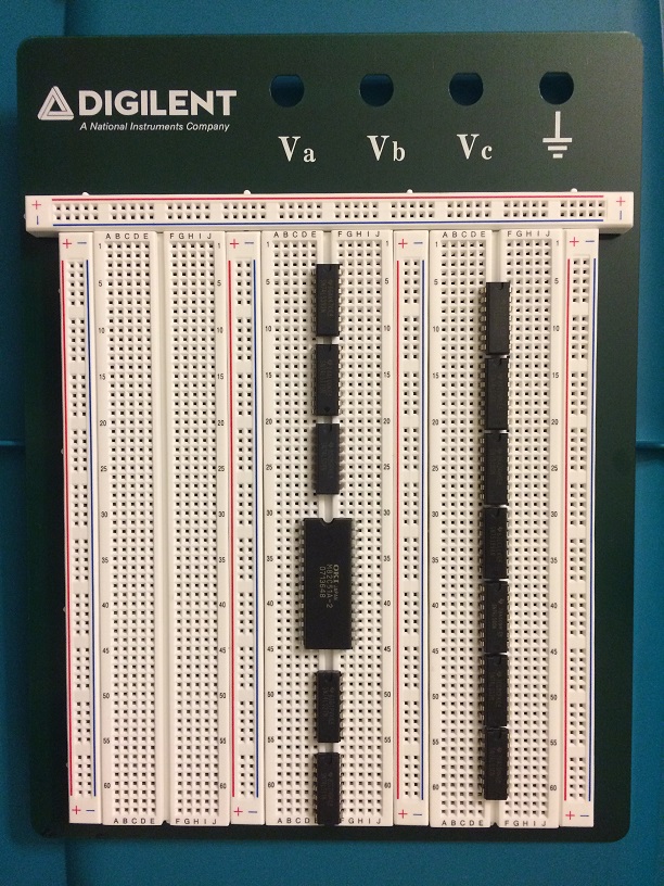
Parts on the Breadboard.
After connecting jumper wires, it became like a sprouts. I wanted to insert an LED for fun, but I just made it exactly as the diagram. I didn't know there was such a thing called Male-to-Female jumper wire extension. So I ended up soldering wires directly on the FCN connector, which was a challenge. But, it might be a better option because soldered wires stay more stable than an extension jumper wire. At least it doesn't slide off.
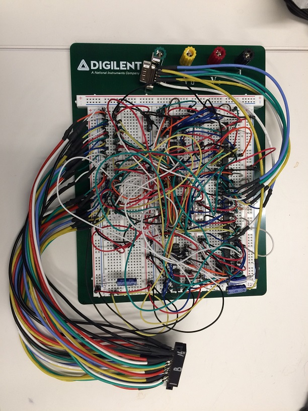
Actually, doing it side by side with KiCad was of big help. Since KiCad comes with a lot of standard ICs specifications, I could confirm those pin numbers were actually correct. I was correctly reading data sheets.
I finished the wiring. But, before plugging it to my FM-7 and test, I wanted to make sure it doesn't fry my FM-7. My FM-7 once spewed smoke during the repair. It survived the last smoke, but next one might permanently kill my FM-7. I tested +5V, GND, +12V, and -12V lines are not directly connected with my tester. And then I tested all networks by looking at the connections on the PCB editor. What I could not test was there is no connections where not supposed to be connected. If I ended up connecting a data pin to +12V or -12V, something may smoke. But, testing all the connections was impossible.
There is no such thing called 100% test. There always is a chance of errors. All we can do is to minimize the probability of a catastrophic failure. I did my best before plugging it to my FM-7.
I was making this breadboard home. I had to bring it to my CMU desk where I am keeping my FM-7. Not to shake it and make wires loose, I hand carried the breadboard to CMU. The best outcome of the day was going to be successfully test the board and confirm the correctness of the schematic. The worst outcome was going to be frying and killing my FM-7 permamently. I did my best. I just had to try.
I connected the FCN connector to my FM-7's expansion slot, and 9-pin connector to a serial-to-USB adapter connected to my laptop. I took a deep breath and turned on my FM-7. If it smokes, it probably would smoke soon after powered on. I saw familiar F-BASIC 3.0 prompt. No smoke was observed. If it works as designed, it should transmit at 19200bps.
I wrote a short F-BASIC program:
10 OPEN "O",#1,"COM0:F8N1"
20 PRINT
#1,"Hello from FM7"
30 CLOSE #1
and RUN.
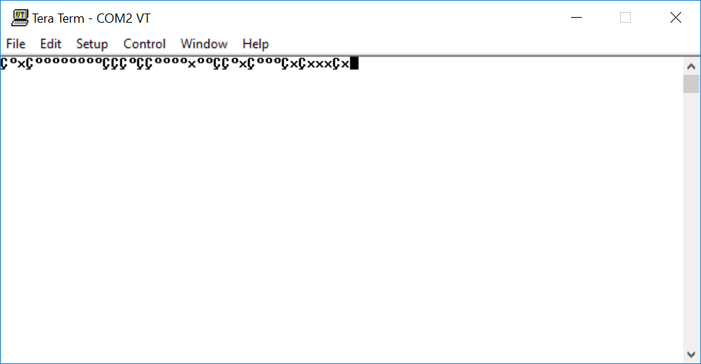
But, the letters were unreadable. I was supposed to see "Hello from FM7". Actually it was somewhat expected. If the clock multiplier of 8251A is not correctly set, it should work at 4800bps. I changed the Tera Term serial port setting to 4800bps, and ran the program again on FM-7, and then,
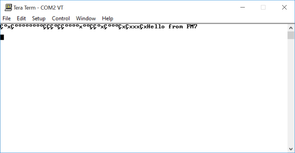
At least the schmatic was good enough to transmit something. After debugging the code, I realized my F-BASIC program was wrong. F8N1 needed to be enclosed by parenthesis. Correct code was this:
0 OPEN "O",#1,"COM0:(F8N1)"
20 PRINT
#1,"Hello from FM-7"
30 CLOSE #1
My RS232C breadboard started transmitting at 19200bps. What about receiving? I have added four lines and tried sending a text from Tera Term:
40 OPEN "I",#1,"COM0:(F8N1)"
50 INPUT #1,A$
60 PRINT A$
70 CLOSE #1
and succeeded. One weird thing was I had to turn off hardware flow-control. Doesn't F-BASIC support flow-control? I tested the same code with FM77AV40 next to my FM-7, and confirmed the same behavior. So, it looks like F-BASIC doesn't support hardware flow-control. That's fine. At least my RS232C board looks to function as same as the original RS232C board.
Since I can omit some wires connected to some pins that are not included in 9-pin serial connector, I was able to simplify the board. I also tested the simplified version, and confirmed it worked. The next step is to get a PCB board and make it a compact expansion card.
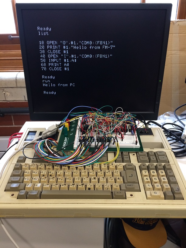
Experiment
Since PCB-printing services take a week or two, the project continued into 2019.
The first version (Ver. 20181225) PCB arrived before the end of the year. My DSUB9's supporting pin fit the hole perfectly.
I haven't soldered parts on a board for looooong time, but soldering went surprisingly well except some sockets were lifted from the board. I first didn't realize my solder was flowing to the other side when the hole was relatively big compared to the pin diameter. I ended up with making a solder ball on the flip side of the DSUB9, but the contact was ok.
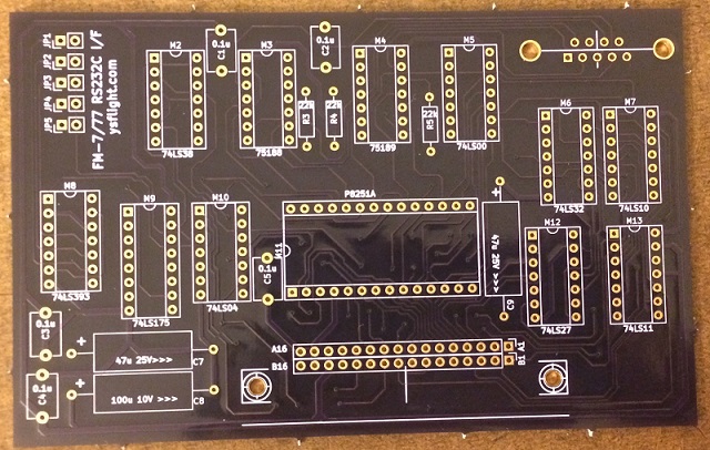
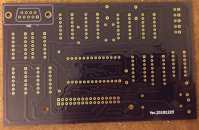
PCB Version 20181225
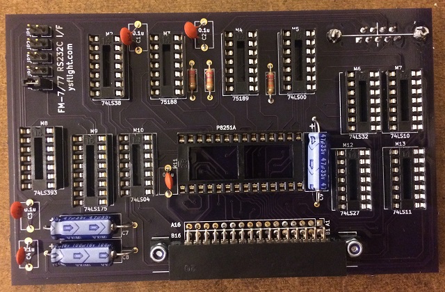
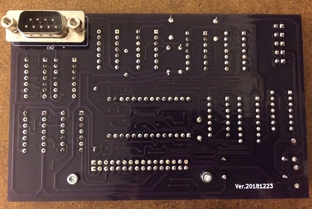
Soldered went surprisingly well.

Except some
sockets were lifted.
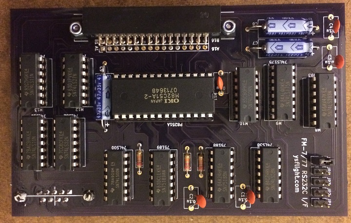
With chips.
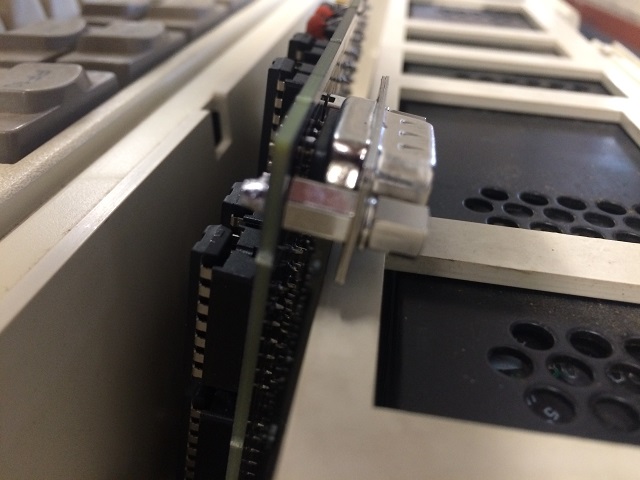
I made sure power supply pins are not leaking and at least pins are connected as designed with my tester. I inserted the card to my FM-7. The FCN connector location was perfect. Everything looks to be good, except I couldn't close the lid. FM-7's lid had a rib. I didn't realize the rib was for stabilizing expansion cards. I was thinking the rib was just for structural strength. My DSUB9 connector was colliding with the rib. I needed to re-design the PCB to move the DSUB9 to the center.
Well, but it should be ok for FM-77 series.
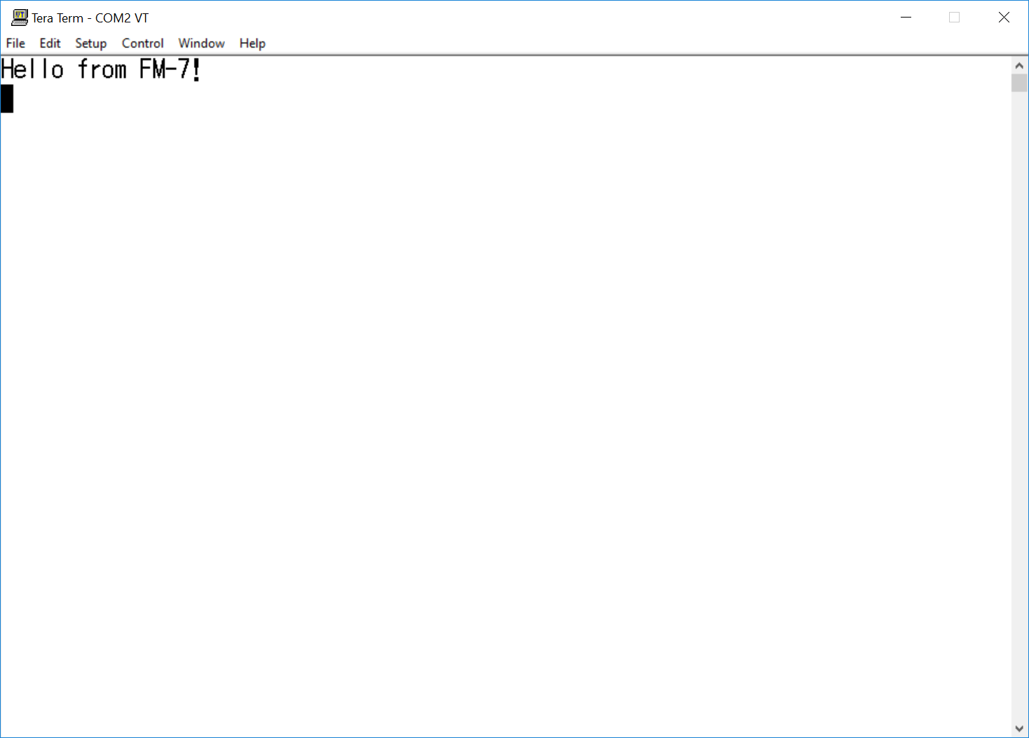
I turned on my FM-7, wrote a simple test code, and ran. Then, The text was transmitted from FM-7 to TeraTerm on Windows side!
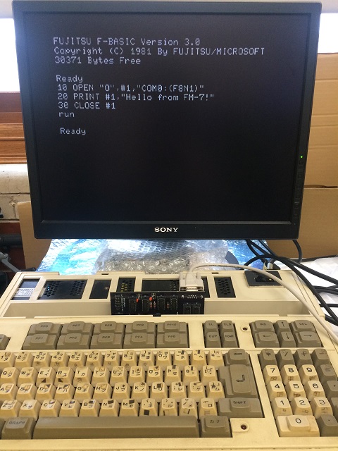
Experiment
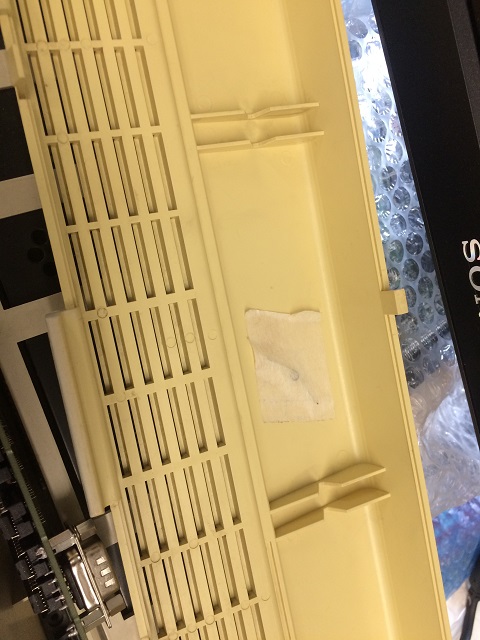
The Rib
SUCCESS! The PCB version functioned perfectly. Now I am able to re-enable RS232C connection for FM-7.
The only problem was the rib-DSUB9 collision. I needed to move it away from the rib.
I re-designed PCB and ordered to OSHPARK on 1/8. It arrived on 1/17.
That day was Thursday, and I bowled in a bowling league. I was bowling way above 200 average in October, but I am like at 185 average for the past a few weeks. Actually I was having less open frames. I used to have 5 to 7 opens in 3 games, but for the past a few weeks I had like 4 opens. But, I couldn't get strikes. All I could get was nine-spare. I can get spares, but my score was suffering. My ball had been hitting pocket after pocket leaving one pin. So frustrating.
After the league, I soldered a board. From the last time, I knew I didn't have to put too much solder when I don't see a nice mountain shape. At least I made sure the hole was closed. To prevent sockets from lifting, I tried to glue sponge on a clamp to hold a socket tightly on the board, which didn't work. My clamp was holding the socket pin and socket. It didn't push the socket on the board. Mr. Apollo again gave an advice to me. I soldered one pin, then held the socket and melted the solder again to put it tight on the board. This method worked well. Well, I ended up soldering M4 socket upside down. It was not a practical problem, but it was an appearance problem.
Then I put it on actual FM-7 and tested. This time I was able to close the lid. Actually my new laptop refused to recognize my USB to RS232C adapter and took several minutes to figure how to fix, but everything else worked perfectly.
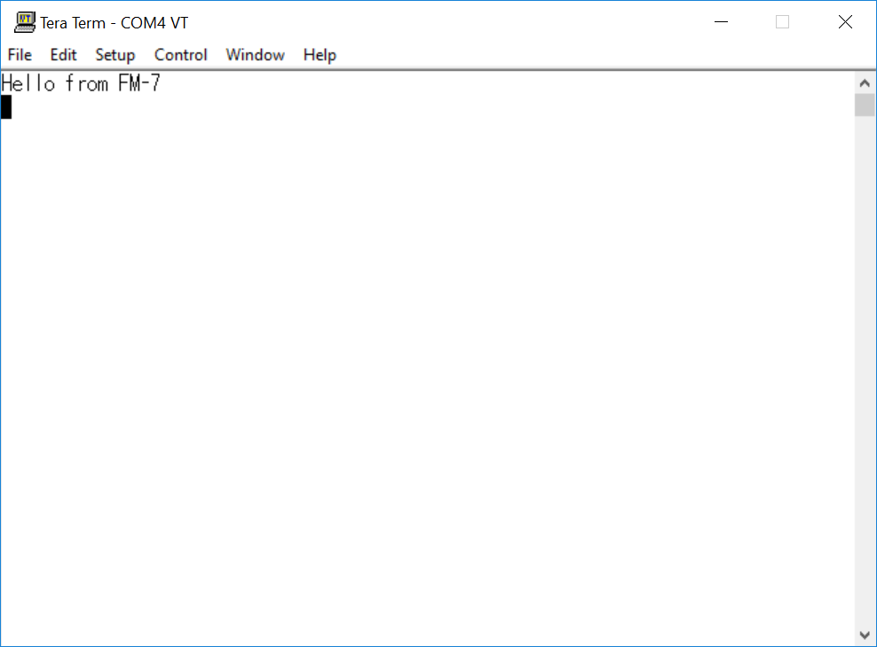
Also succeeded to transmit text from Windows 10 to FM-7. Now I am able to write back D77 floppy disk image via RS232C on all of my FM-7, FM77AV, or FM77AV40. System redundancy.
I succeeded in overriding BIOS of FM-7 and load programs in T77 tape image via RS232C. I have tested Delphis, Dragon Slayer, and Emergency. This enables AV40SX model, which doesn't have a tape interface connector to load and run tape-based titles. I'm going to release the programs in YSFLIGHT.COM soon.
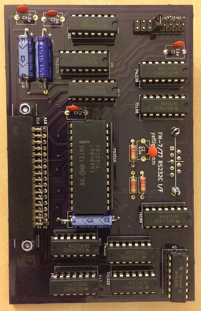
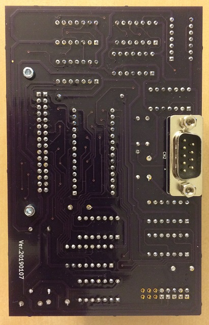
New PCB. I bent legs of M5 when I was inserting. It didn't impact the functionality, but appearance....
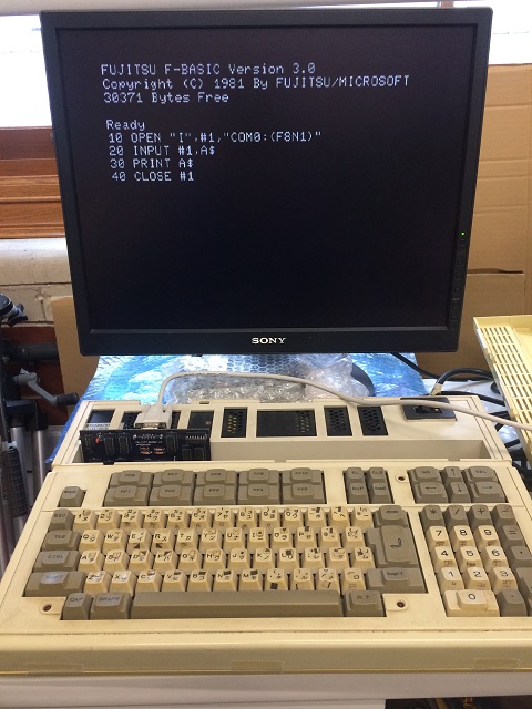
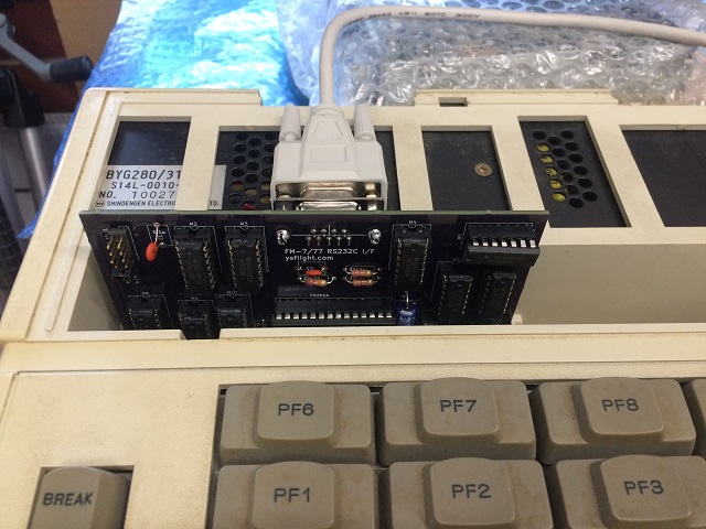
Experiment
| Comments are welcome.
Send E-Mail to:
|