Cessna 172R Flap and Aileron
Polygon Crest is a fre and open-source program.
Therefore, you can use it for free of charge. However, I appreciate if you
donate some money for supporting the development. For making donation,
please send some money via PayPal using the following button.
I will use the donated money for upgrading my developing
environment, buying books for learning new programming techniques, maintaining
and adding contents in YSFLIGHT.COM. Thank you for your support!
In this example, you can cut out a flap and an aileron from
the main wing created
in the previous tutorial.
An aircraft flap is typically retracted underneath the main wing, and
extended when the pilot moves the flap lever. When extended, the flaps
effectively increase the area of the wing. For making a part for the flap,
it is possible to use a boolean operation to separate a volume for a flap from
the main wing. But, making a volume for cutting out may not be straight
forward. In this case, it is easier to directly splitting some polygons,
cut them out to the new shell, and directly manipulate the shape.
The overview of the steps are as follows.
- Split some polygons to cut out.
- Cut & paste some polygons to a new shell and do some manipulation in the
new shell to create a flap.
- Copy & paste some polygons of the new shell back to the original shell
to close opening of the main wing.
- Do similar operation for an aileron.
- Fill the opening of the main wing to make it closed.
Download Sample Wing Model
C172R_mainwing.srf
If you open this sample model, you will see:
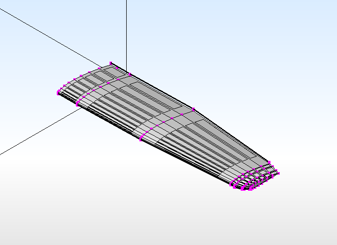
Splitting Polygons that becomes a Flap and Aileron
- Press F2 key, or click on "Bottom" button on the view-control dialog to
look at the wing from the bottom.
- Press V key, or select [Edit]->[Insert]->[Vertes] to enter
vertex-insertion mode.
- Move the cursor close to X=-0.44, Z=1.05 with the mouse left button.
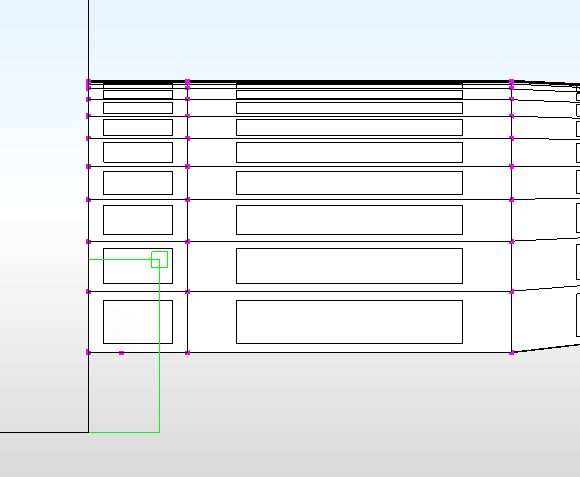
- Press F1 key, or click on "Front" button on the view-control dialog to
look at the wing from the front.
- Use mouse right button to move the cursor close to Y=0.4, and press
space or click on [Insert] button. You get a new vertex.
- Keep the viewpoint as is, and use mouse right button to move the cursor
close to Y=1.25, and press space or click on [Insert] button to get the
second vertex.
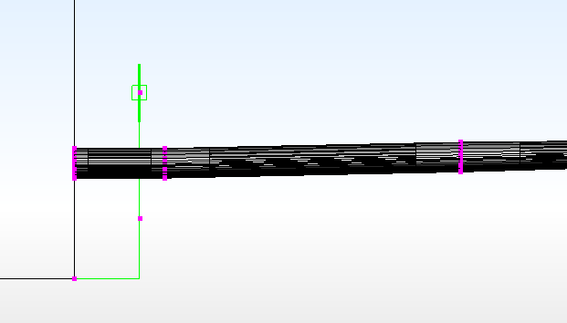
- Press Shift+V key, or select [Selection] -> [Pick] -> [Vertex] and
select the two vertices that you created, and then select [Edit] -> [Create]
-> [Parallelogram from Two Selected Vertices].
- From the front view (if the view rotated, press F1 again) use mouse left
button to move the cursor close to X=-2.7.
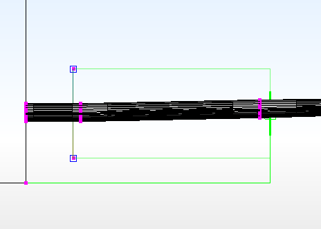
- Press Space key, or click on [OK] button.
- Press T key, or select [Select] -> [Unselect] -> [Unselect All] to
unselect the two vertices.
- Press Shift+F key, or select [Select] -> [Pick] -> [Polygon], and click
on the new polygon created in steps 6 through 9.
- Select [Edit] -> [Intersection] -> [Cut by Plane].
- Press Delete key, or select [Edit] ->[Delete] -> [All Selection] to
delete the polygon. (This polygon is no longer needed.)
- Press F2 key, or click on "Bottom" button on the view-control dialog to
look at the wing from the bottom.
- Press V key, or select [Edit]->[Insert]->[Vertes] to enter
vertex-insertion mode.
- Use mouse left button to move the cursor close to X=-5.45, Z=1.225.
- Press F1 key, or click on "Front" button on the view-control dialog to
look at the wing from the front.
- Use mouse right button to move the cursor close to Y=0.4, and press
space or click on [Insert] button to create a new vertex.
- Move the cursor close to Y=1.25, and press space or click on [Insert]
button to create a new vertex.
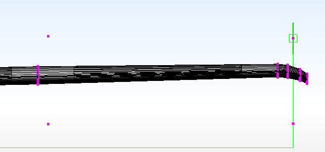
- Select the new vertex underneath the wing, and then the one above the
wing.
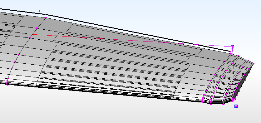
- Rotate the view so that the upper side of the wing is visible, and
select a vertex created in Step 7 (as shown below)
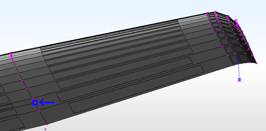
- Rotate the view so that the under side of the wing is visible, and
select the vertex shown in the next picture.
- Press F key, or select [Edit] -> [Insert] -> [Polygon] to create a
polygon.
- Select the polygon created in step 23, and then select [Edit] -> [Intersection] ->
[Cut by Plane].
- Press Delete key, or select [Edit] ->[Delete] -> [All Selection] to
delete the polygon. (This polygon is no longer needed.)
Making a Flap
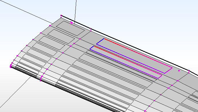
- Rotate the view so that you look at the top-side of the main wing and
select the polygons highlighted below.
- Rotate the view so that you look at the bottom-side of the main
wing and select the following polygons.
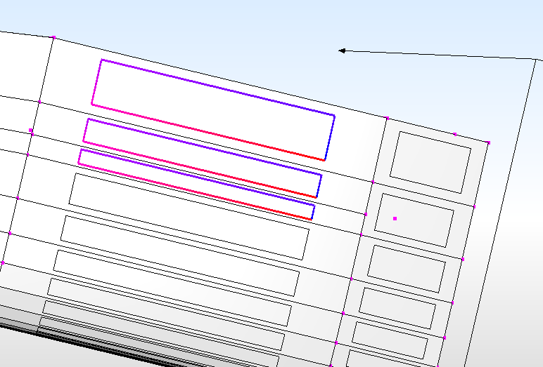
- Press Ctrl+C key or select [Edit] -> [Copy]
- Press Delete key or select [Edit] -> [Delete] -> [All Selection]
- Select [File] -> [New]
- Press Ctrl+V key or select [Edit] -> [Paste]
- Press T key or select [Select] -> [Unselect] -> [Unselect All]
- Select the following two vertices.
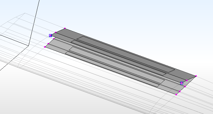
- Press F3 key or click on the [Left] button on the view-control dialog.
- Select [Edit]->[Create]->[Parallelogram from Two Selected Vertices].
- Move the cursor by left-button drag to about the location that matches
the front-most vertex and press Space key or click on the [OK] button.
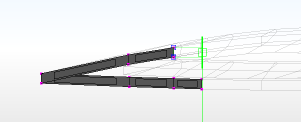
- Press T key or select [Select]->[Unselect]->[Unselect All]
- Select the following 4 vertices, and press F key or select
[Edit]->[Insert]->[Polygon]
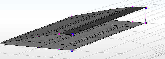
- Select the two vertices as shown below and select
[Edit]->[Round]->[Along Selected Const-Edge or Vertex Sequence]

- Set the radius to 0.07 by the slider, and press Space key or click on
[OK] button.
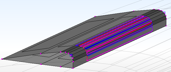
- Select the following polygons and press Ctrl+C key or select
[Edit]->[Copy]
- Press Ctrl+Tab key to switch to the main-wing model.
- Press Ctrl+V key or select [Edit]->[Paste]
- [Global]->[Merge Vertices at the Same Location], and click on [OK]
button on the dialog.
- Press Ctrl+Tab key to go back to the flap model.
- Press T key or select [Select]->[Unselect]->[Unselect All]
- Select two vertices as shown below.

- Select [Edit]->[Round]->[Along Selected Const-Edge or Vertex Sequence]
- Set radius to 0.05 by the slider and press Space key or click on [OK]
button.
- Press T key or select [Select]->[Unselect]->[Unselect All]
- Select the following vertices, and then press X key or select
[Select]->[Vertex]->[Follow Single Use Edge Loop] multiple times until all
vertices on the side of the flap are selected.

- Press F key or select [Edit]->[Insert]->[Polygon]
- Do the same thing (steps 26-27) for the other side of the flap.
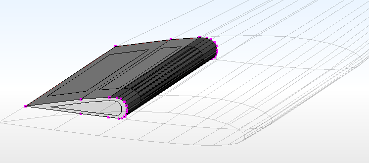
- [Global]->[Recalculate Polygon Orientation]
- Flap is complete.
Making an Aileron
- Press Ctrl+Tab to switch to the main-wing model.
- Press T key or select [Select]->[Unselect]->[Unselect All]
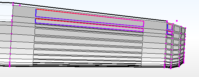
- Rotate the view point so that the upper-side of the wing is visible, and
then select the polygons below.
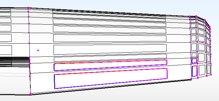
- Rotate the view point so that the bottom-side of the wing is visible,
and then select the polygons below.
- Press Ctrl+C key or select [Edit]->[Copy]
- Press Delete key or select [Edit]->[Delete]->[All Selection]
- Select [File]->[New]
- Press Ctrl+V key or select [Edit]->[Paste]
- Press T key or select [Select]->[Unselect]->[Unselect All]
- Select the following vertex (1) and then (2).
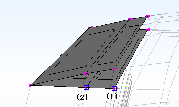
- Press X key or select [Select]->[Vertex]->[Follow Single-Use Edge] 3
times.
- Press F key or select [Edit]->[Insert]->[Polygon]
- Rotate the view so that the other side is visible, and then select the
following vertex (1) and then (2).
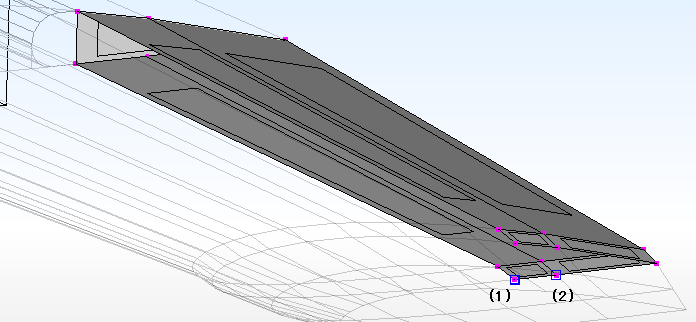
- Press X key or select [Select]->[Vertex]->[Follow Single-Use Edge] 3
times.
- Press F key or select [Edit]->[Insert]->[Polygon]
- Select the vertex as shown below and then press X key or select
[Select]->[Vertex]->[Follow Single-Use Edge] 5 times.
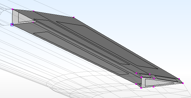
- Press F key or select [Edit]->[Insert]->[Polygon]
- 「全体処理」-> 「全ポリゴンの巻き方向を再計算」を選ぶ。
- エルロン完成。
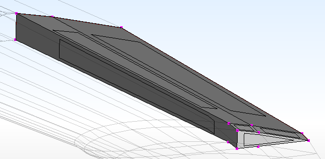
主翼本体のポリゴン欠落部分を埋める
- Ctrl+Tabキーで、主翼のモデルに切り替える。
- Tキーを押す、または、「選択」-> 「選択解除」-> 「選択解除」を選んで選択解除。
- 翼の付け根側のポリゴン欠落部分の1頂点を以下の図のように選択。
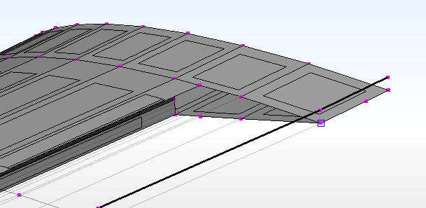
- 欠落部分の頂点一周分が選択されるまで、Xキーを押すか、「選択」-> 「頂点」-> 「バウンダリに沿って選択」を選ぶ。
- Fキーを押すか、「編集」-> 「頂点」-> 「ポリゴン」で、ポリゴンを作成。
- 翼端側、欠落部分の2頂点を(1)、(2)の順で以下の図のように選ぶ。
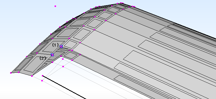
- Xキーを3度押すか、「選択」-> 「頂点」-> 「バウンダリに沿って選択」を3度選ぶ。
- Fキーを押すか、「編集」-> 「追加」-> 「ポリゴン」で、ポリゴンを作成。
- 翼中央付近、次の図の2頂点を、(1)、(2)の順に選択。
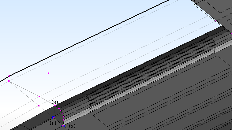
- 図の頂点(3)が選択されるまで、Xキーを押すか、「選択」-> 「頂点」-> 「バウンダリに沿って選択」を選ぶ。
- Fキーを押すか、「編集」-> 「追加」-> 「ポリゴン」で、ポリゴンを作成。
- 上の図の頂点(1)を選択。
- 残りの欠落部分の頂点がすべて選択されるまで、Xキーを押すか、「選択」-> 「頂点」-> 「バウンダリに沿って選択」を選ぶ。
- Fキーを押すか、「編集」-> 「追加」-> 「ポリゴン」で、ポリゴンを作成。
- 「全体処理」-> 「全ポリゴンの巻き方向を再計算」を選ぶ。
- 主翼完成。
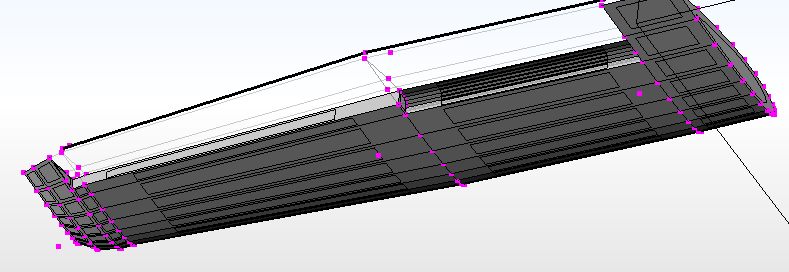
主翼、フラップ、エルロンは、後でDNM形式ファイルにまとめるために、それぞれ別の.SRFファイルとして保存しておく。


